NetApp Simulator Setup
Update 10/09/2020
Initially I wrote this guide to use the ONTAP 9.7 simulator, but after one month of struggling and issues with the snapmirror relationship between the two simulators I do recommend to use 9.5 (the one officially supported for vSphere) instead. I’ll update the article with screenshots and settings from 9.5 soon.
The Plan
I want to set up two NetApp ONTAP Simulators in my vSphere lab environment. I’ll have them run each as individual ONTAP clusters with one SVM and peer them, so the primary NetApp can snap mirror and vault to the secondary.
If you want to follow make sure to have some resources. Running two simulators will take at least 4 cores, 16GB RAM and disk space depending on your needs. Thick provisioned they’ll take ~240GB per node.
Preparation
You’ll require a NetApp account to download the simulator (or find the sources somewhere in the web). For the official source, you can go to the NetApp download portal, accept the EULA and download simulators for ONTAP 9.5, 9.6 and 9.7.
Use 9.5 here when running it on vSphere. Later versions might work on vSphere but officially NetApp only supports 9.5. The newer versions are only supported on VMware Workstation, Player and Fusion.
I tried it with ONTAP 9.7 and while the simulators ran good initially the target always died when initiating a snapmirror relationship.
Next to the OVA download you’ll also find the CMode_licenses_9.5P6.txt. Be sure to grab that, too.
Installation
Cluster Setup
So deploy the OVA on your vSphere environment. I won’t go into much detail here. They’ll ask for two networks within the process and attach each of these networks to two vNICs in the VM. The hostonly network is intended for internal cluster traffic while the nat network is the one you can reach from outside (management & payload).
I’ll reconfigure these interfaces later to match my purpose, but for now make sure to configure your management port group on the nat network.
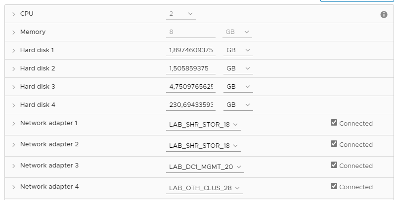
As I have plenty of memory I deploy the VM with 8GB instead of the default 5.1 and I reconfigure the vNICs for the three networks I want to use.
The vNICs will be mapped to e0a, e0b, e0c and e0d in order of appearance. e0c (Network adapter 3) is the default for the management network in the upcoming cluster setup, so I’ll keep my management network there.
The first two are connected to my storage payload port group for iSCSI and NFS traffic while the last one is dedicated to cluster-to-cluster traffic (NetApp to NetApp sync).
Configuration
Time to start our new NetApp. When you have a DHCP on your management network you’ll likely get advertised to go to https://some-ip to setup the cluster. Otherwise you can login at the prompt with admin. You won’t need a password. I choose to configure the initial node management IP on the CLI before going to the web frontend.
Logged in as admin, the next thing you want to do is run the cluster setup command which will ask you for the config of your management network. As soon as you gave IP, subnet and gateway you can continue the rest of the cluster setup via the browser. This IP will be your node IP (I’ll have only a single node cluster), so make sure to pick the right one if you have a nice schema in your Homelab and you want to everything nice and tidy. You’ll give an IP to the cluster later.
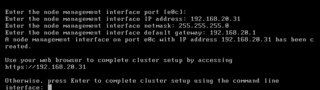
cluster setup on the CLI helps you to configure the management IP.When continuing on the browser wizard, make sure to type the HTTPS in front of the IP, as there’s no insecure version of this site.
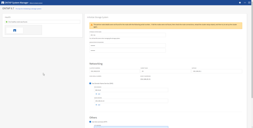
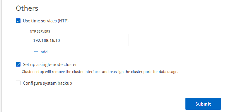
On wizard page give your new cluster a name, an IP address and I also recommend to configure DNS and NTP.
It is important to tick the Set up a single-node cluster which will give you the previously blocked cluster interfaces for other use.
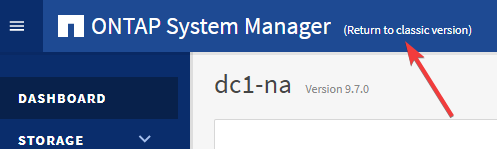
When the cluster setup is done you are redirected to the ONTAP System Manager on the configured cluster IP address and can login with username admin and your configured administrative password.
Here you can easily add the licenses from the downloaded .txt file but the next click should bring you to the classic version of the System Manager.
All upcoming descriptions are based on the classic version of the System Manager unless noted otherwise.
More space for ONTAP
First thing we do is give the whole system some space to breathe and work. After the cluster setup I only have like 40MB free space left on my 855MB root aggregate (where the OS volume lives), so we’ll need to extend that.
The simulator comes with 28 x 1GB disks. On 3 of these the ONTAP OS is installed (above mentioned root aggregate), 11 more are already claimed for the current node and there are still 14 unassinged disks. Go to Storage > Disks and you’ll directly get a yellow warning about these disks.
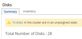
Clicking the link will bring you to the inventory tab where you can just select all disks and assign them all to your node.
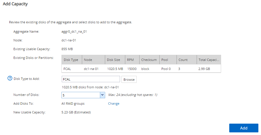
After this go to Storage > Aggregates and select your root aggregate (aggr0_dc_na_01 in my case). It’s the only one present.
Choose More Actions and Add Capacity to add more disks to the root.
I chose to add 5 disks to get a new usable capacity of just above 5GB.
Now that’s something we can work with. To extend the OS volume to the new aggregate size, we need to go down to the CLI. The following commands change from the cluster to the node perspective and set the size of the OS volume vol0 to 4750 Megabyte (93% of the aggregate, 95% is the maximum allowed).
node run -node local
vol size vol0 4750m
More space to use
With the remaining 20 disks you can create a RAID-DP with about 15GB (out of 19 disks, 1 is spare). If this is enough for your use, you can pass on to the next section, otherwise read on to add some more virtual disks.
Back on the cluster level shell we use the following command to add 14 (-n 14) additional disks of type VD-9000MB-FZ-520 (-t 36) to adapter 2 (-a 2).
set diag
systemshell local "cd /sim/dev;sudo vsim_makedisks -t 36 -n 14 -a 2"
reboot local
There are 4 adapters numbered 0-3 in the system, but 0 and 1 are already fully populated and each adapter can take 14 disks. So you can add another 14 disks to adapter 3 (-a 3) before running the reboot if you like.
Also you can get a list of available disk types by running the following command. Though 9GB disks are the largest you can get.
set diag
systemshell local vsim_makedisks -h
Assign the new disks to the node after the reboot.
Create Aggregate
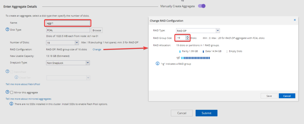
Go back to Storage > Aggregates and create a new one. Click the Manually Create Aggregate button on the right top corner of the wizard to be able to modify the aggregate settings. The screenshots will show the process with the alreay present 1GB disks.
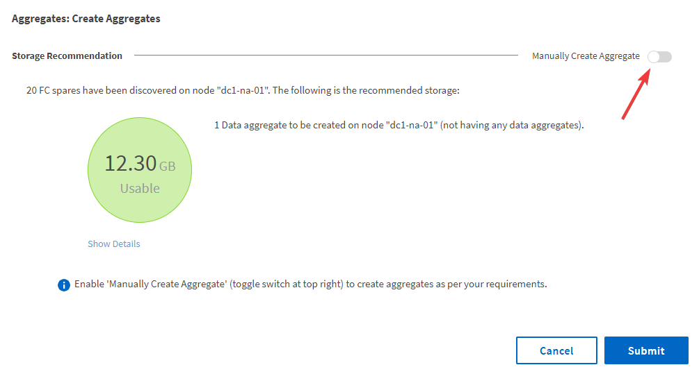
Give the aggregate a name (e.g. aggr1), and adapt the number of disks and RAID group size settings to get the results you want. For the pre-configured 1GB disks I want to achieve best usable capacity, so I configure all disks (19 in my case) and I change the RAID configuration to a RAID group size of 19 to have the maximum output for your disks (14.94 GB). Then create the aggregate.
Create Storage Virtual-Machine (SVM)
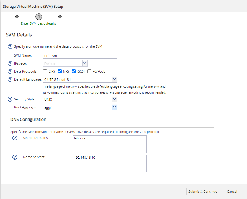
Navigate to Storage > SVMs and create a new one.
Give it a name, tick the protocols you want to provide and choose the root aggregate where the SVM root volume should reside (I’ve chosen aggr1 which is the 15GB volume coming from the shipped disks). DNS comes from the cluster config.
I want to use my NetApp simulator as a vSphere datastore, so this is either NFS or iSCSI.
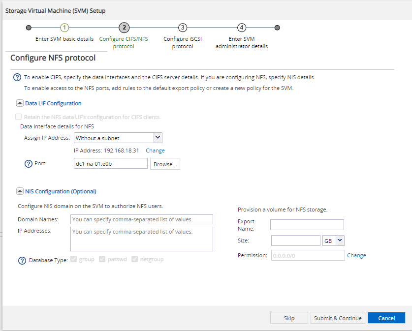
On the next wizard page we create a logical interface (LIF) which can be used to access the NFS service of the SVM. I choose to assign the IP address without a subnet (enter it manuall) and select a port on which this interface should communicate.
This is an IP from my storage payload subnet (192.168.18.0/24) and should connect to the corresponding network which is on e0a ande0b based on my VMware config. I’ve chosen e0b for my NFS traffic.
I do net yet create a volume for NFS because the options in this wizard are limited.
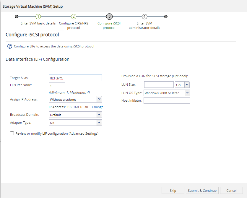
Same thing for iSCSI on the next page. Select the Default broadcast domain and change the Adapter Type to NIC. Configure a static IP without a subnet. If you want to specify which NIC to use for the LIF you can tick the Advanced settings button below. When only one is created, e0a is the default.
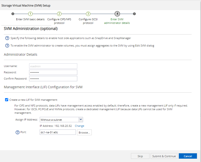
On the last wizard page you’ll be asked for managemend details. That’s not always necessary, but as I want to add my SVM to Veeam later, I want to have a management IP and credentials. I’ve chosen an IP from my management subnet (192.168.20.0/24) and connected it to e0c (same as my cluster and node management interfaces).
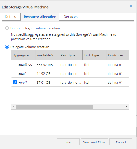
After the summary close the wizard and directly click the edit button on the new SVM. Navigate to the Resource Allocation tab and delegate volume creation for the aggregate you want to have your data on:
Rewind & Repeat
All the steps up until now should be also done for your second NetApp simulator VM, so that we can use it as a peering target later on. Run the following tasks only on the primary system.
Make sure to use unique names for each cluster and SVM, so that you can easily identify them (and avoid issues later on).
iSCSI Configuration
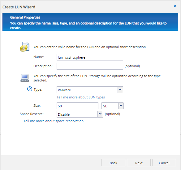
Now let’s set up an iSCSI target for my ESXs. Navigate to Storage > LUNs and create a new one. In the wizard continue with defaults up to the General Properties. Here change the type to VMware, specify a size you want to have and disable the space reserve to enable thin provisioning of the LUN.
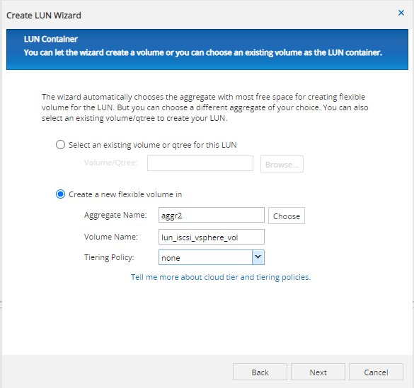
Next you chose on which aggregate to create the volume for the LUN. I set the Tiering Policy to none as I don’t use it.
Create a new initiator group of type VMware and add the IQN of the ESX server in the initatiors list (just copy & paste into the big text box).
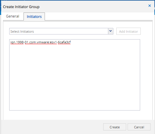
Don’t forget to tick the Map checkbox, so you’re initiators will get that new LUN presented. I left the rest of the wizard on defaults and got my LUN and volume set up and my iSCSI is ready to use from the ESX server via the LIF IP you configured for iSCSI.
NFS Configuration
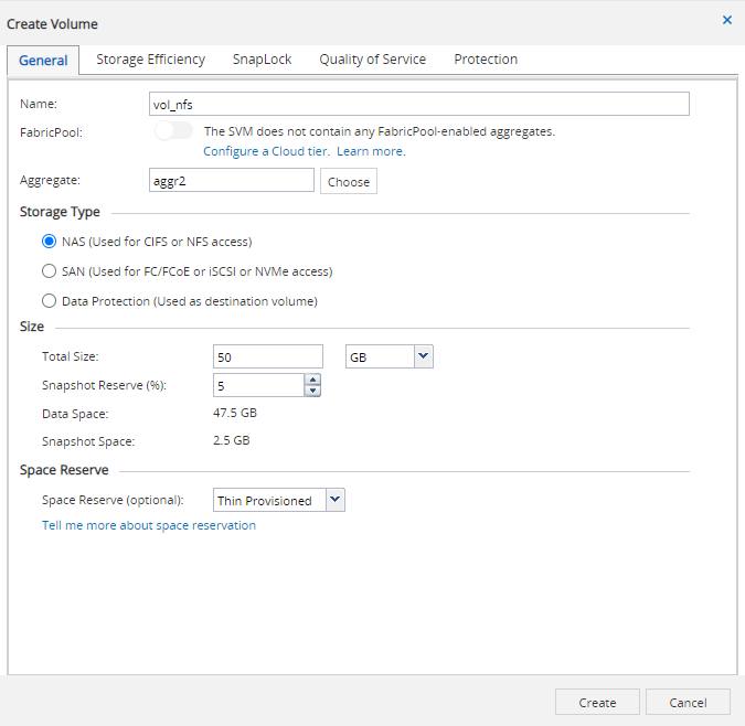
Navigate to Storage > Volumes and create a new one, choose the appropriate aggregate and storage type NAS. Choose a size and snapshot reserver (the default is just fine) and select Thin Provisioned at the Space Reserve option. I did not touch any setting on the other tabs.
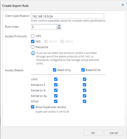
Now go to Storage > SVMs and down to SVM Settings > Export Policies. Here click on the default policy and add a new entry on the bottom of the page to allow NFS access for your host(s)
Now you can add the NFS share to your ESX server. The export name will be based on the chosen volume name and can be reviewed at Storage > Junction Paths. Use the LIF IP you’ve chosen for NFS before.
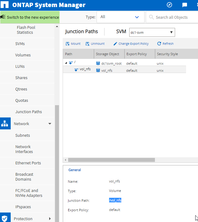
Junction Paths section you can review the export path for NFS shares.Summary
This ends the first part of this howto. I have a primary NetApp simulator running which provides one NFS and one iSCSI datastore to my vSphere environment which I can already use.
The second simulator is on standby to be configured as a peer for snap mirror / vault.
Sources
These are the sources I used to create this article:
One Reply to “NetApp Simulator Setup”
Comments are closed.